Listing Program At89s51
Posted : admin On 17.09.2019
At89s51 Programmer
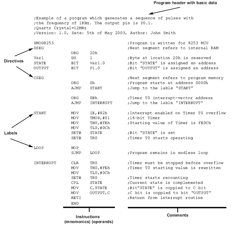
LED blinking is the most basic project to see a physical output through a microcontroller. One can understand the concept of IO configurations of the GPIO port in a microcontroller with the simple LED blinking project. In this chapter, we will learn about the interfacing, circuit. Program yang telah selesai kita buat dapat disimpan dengan ekstension.asm. Lalu kita dapat membuat program objek dengan ekstension HEX dengan menggunakan compiler MIDE-51, yang dijelaskan sebagai berikut: 1.7.2 Assembly Listing Program-sumber assembly di atas, setelah selesai ditulis diserahkan ke program Assembler untuk diterjemahkan.
We are selling a Project Kit for this Water Level Controller which can be bought from our Online Store. The project kit is a modified version of the project shown above. This Water Level Controller project kit uses 4 float switches to measure water level. The status of water level in the tank and status of the motor is displayed using an LCD module.
This system monitors the water level of the tank and automatically switches ON the motor whenever tank is empty. The motor is switched OFF when the overhead tank or container is FULL. Hello Abdul, you just cant replace 8051 with PIC or any other micro controller like AVR.
Listing Program Mikrokontroler At89s51
The reason is difference in “hardware architecture”. You can consider replacing the AT89S51 (from Atmel) microcontroller we have used in the circuit with other controllers of similar architecture – say AT89c52 or some other controllers. The controller must be compatible with MCS-51 instruction set too. If you are planning to use PIC, you can do so by rewiring the circuit in accordance with PIC architecture. You will also have to rewrite the codes based on PIC instruction set.
. Description: This application note describes the general hardware configuration and basic software communication examples for the Dallas I2C serial-interface Real-Time Clocks (RTC). The devices covered are the BCD-format I2C clocks:, DS1337, DS1338, DS1339 and DS1340.
The DS1375 could also be supported, if circuit modifications were made to provide a digital clock signal (32,768Hz, 8,192Hz, 60H, or 50Hz) to the CLK input pin. The microcontroller used for this example is the DS2250, and the example software is written in C. A schematic of the circuit is shown in Figure 1. The schematic shows connections for a DS1340. Christine Mohrmann. The other RTCs may require modifications.
The DS1337, for example, replaces the battery back up input with an additional interrupt output. The low voltage versions of the RTCs would require replacing the DS2250/DS5000 with a suitable low-voltage microcontroller. Figure 2 shows the software listing. The #define directive is used to conditionally compile the code for the proper device. The example shown is for the DS1307.

The #define statement for the DS1307 should be replaced with the correct device before compiling the code Code.